Table of Contents
Adding an ASD Relay to the Fuel Pump Relay Output
Many vehicles have an auto-shutdown (ASD) relay that provides power to the ignition coil and fuel injectors. For safety purposes, it's best that Megasquirt controls this relay. The same logic that controls the fuel pump relay can be used to control an ASD relay, but unfortunately a Megasquirt ECU's fuel pump relay output cannot sink current from both. Here are a few techniques for connecting both an ASD relay and a fuel pump relay to a Megasquirt ECU's fuel pump relay output.
Before learning these techniques, it may be helpful to first review the fundamentals of relays.
Daisy-chain Existing Relays
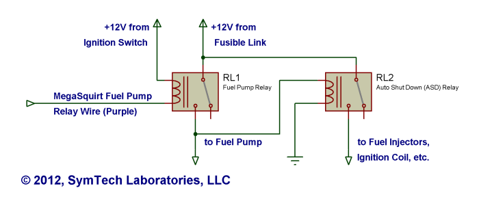
In cars with remotely mounted, socketed and hard-wired ASD and fuel pump relays, such as the 420A Eclipses and Talons, it's possible to daisy-chain the two relays. In other words, the Megasquirt ECU's fuel pump relay output switches the coil of the fuel pump relay. The fuel pump relay's armature, in turn, provides power to the fuel pump relay and the ASD relay's coil.
- Begin by identifying the two relays and familiarizing yourself with their connections. Specifically, identify their coil connections to +12v, from the fusible link, and to the stock PCM.
- Cut the wire connecting the fuel pump relay's coil to the stock PCM, and connect it to the fuel pump relay output from your Megasquirt ECU.
- Next, cut the wire connecting the ASD relay's coil to the stock PCM and connect it directly to chassis ground.
- Finally, cut the wire connecting the ASD relay's coil to +12V and connect it the fuel pump relay's COM pin, which should also be directly connected to the fuel pump.
Add a Third Relay
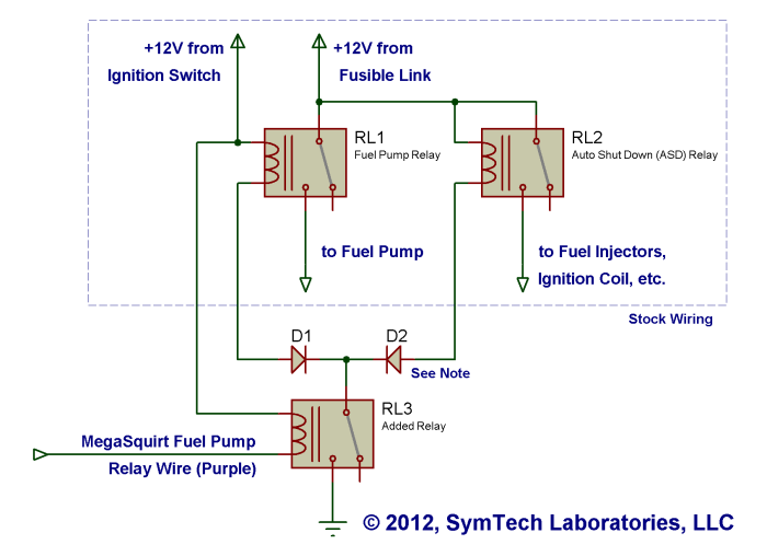
In cars with power distribution centers (PDC), such as the Dodge Neon, the ASD and fuel pump relays are mounted in a static enclosure and draw +12V from connections to a heavy busbar. These connections are impossible to rearrange without devoting a significant amount of time to re-engineering the PDC. The quickest and easiest solution here is to add a third relay to switch both the ASD and fuel pump relays.
- Obtain any standard 12VDC automotive relay, capable of switching at least 2A.
- Connect one of the relay's coil pins directly to the fuel pump relay wire in your MegaSquirt harness.
- Connect the other coil pin to a fused +12V source. There are several suitable locations inside the PDC.
- Connect the common pin to chassis ground.
- Identify the ASD and fuel pump relays and familiarize yourself with their connections. Specifically, identify their coil connections to the stock PCM.
- Cut both wires connecting the ASD and fuel pump relays' coils to the stock PCM, and connect them both to the normally open (NO) pin of the added relay.
- Some cars, such as the Dodge Neon, require two diodes to be added as depicted below. If the diodes are omitted, current could flow through the ASD and fuel pump relays' coils despite the third relay being deactivated.
- The ubiquitous 1N4001 rectifier diodes (RadioShack part #276-1101) work well.
- Signal diodes (1N914, 1N4148, etc.) are not suitable.
Parallel Existing Relays
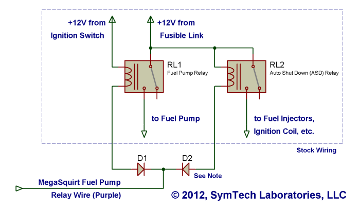
Like adding a third relay, connecting both of the existing relays to the fuel pump relay output is a good solution for cars with power distribution centers (PDC). This method is only feasible if the resistance across pins 85 and 86 of both relays is 40 ohms or greater.
- Identify the ASD and fuel pump relays and familiarize yourself with their connections. Specifically, identify the coil connections to the stock PCM.
- Cut both wires connecting the ASD and fuel pump relays' coils to the stock PCM, and connect them both to the fuel pump relay wire in your MegaSquirt harness.
- Some cars, such as the Dodge Neon, require two diodes to be added as depicted below. If the diodes are omitted, current could flow through the ASD and fuel pump relays' coils despite the MegaSquirt ECU being powered down.
- The ubiquitous 1N4001 rectifier diodes (RadioShack part #276-1101) work well.
- Signal diodes (1N914, 1N4148, etc.) are not suitable.
Replace the Internal Relay Driver
Your Megasquirt ECU's internal ZTX450-based fuel pump relay driver may be upgraded to control both the ASD and fuel pump relays. Please be aware that modifying your SymTech Labs Megasquirt ECU may void its warranty. Also, if your car requires the two diodes as outlined in the previous section, it will require those diodes using this method as well.
The ZTX450 transistor (Q2) can be replaced with either a ZTX650 transistor or TIP120/TIP122 Darlington pair transistor (RadioShack part #276-2068). Begin by removing Q2, Q19, and R40. Replace R40 with a short length of jumper wire.
The ZTX650 can be installed in place of Q2; it is a direct replacement for the ZTX450.
The TIP120/TIP122, however, should be securely mounted on the ECU's heat sink with thermal paste, electrically isolated using a mica insulation kit. Trim the legs of the TIP120/TIP122 to a manageable length to prevent accidental shorts. Using jumper wire, connect each leg of the TIP120/TIP122 to its corresponding through-hole in Q2's location. Keep in mind that the ZTX450's pin assignment (1 - emitter, 2 - base, 3 - collector) is different than the TIP120/TIP122's pin assignment (1 - base, 2 - collector, 3 - emitter).